Object Diagrams
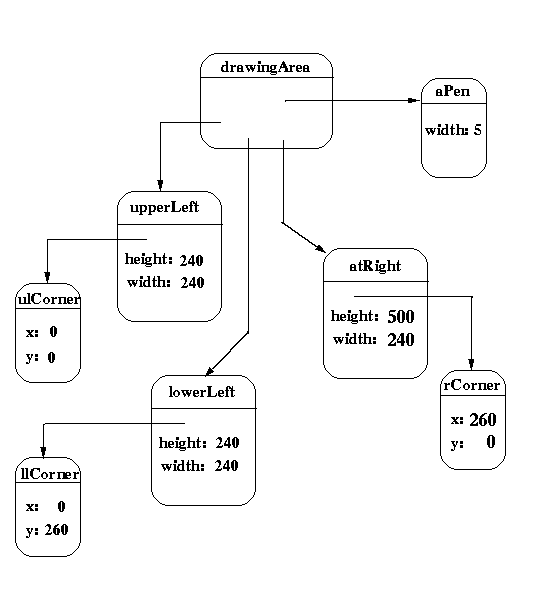
Suppose that an application has a drawing area that is 500 pixels in
both height and width that is dived into three regions as follows:
- the right (approximately) half of the drawing area is a single
region bordered by a rectangle. The upper left hand corner of this
region is at coordinates (260, 0), its width is 240 pixels, and it
height is 500 pixels.
- the left (approximately) half of the drawing area is subdivided
into two equal size regions each of which is bordered by a
rectangle. The upper left corner of the top subregion is at
coordinates (0,0). The upper left corner of the botton subregion is
at coordinates (0, 260). Each subregion has a width and height of 240
and 240, respectively.
The border should be drawn with a thickness of five pixels.
Using the classes mentioned earlier ,
the drawing area could be implemented by a Canvas object, each of the
three drawing regions by Rectangle objects, and the border width would
be handled by associating an appropriately initialized Pen object with
the Canvas object.
The class diagram shown earlier does
not convey some essential information about the structure of the
drawing area. For example, the class diagram does not indicate:
- the Shapes known by the Canvas are specifically Rectangles,
- there are exactly 3 Rectangle objects known by the Canvas,
- the location of each Rectangle object, and
- the value of the Pen object's width.
Answers to questions such as these are provided in an object diagram.
An object diagram for the example is shown below. The drawingArea
object is an instance of the Canvas class and has pointers to three
Rectangle objts (upperLeft, lowerLeft, atRight). Each of the Rectangle
objects has a composed Location object. Since the diagram depicts
objects, the actual values of each Rectangle object's Location, height
and width can be shown in the diagram. Also, the width of the Pen
object (aPen) used by the drawingArea object can be shown explicitly.
Last Updated: December 13, 1995 / kafura@cs.vt.edu