- What is a bit plane?
- Given a display with the following characteristics:
- 1024x768 addressable pixels
- 24 bit color
- 60Hz refresh rate
(A) How much memory is required to store the pixmap?
(B) At what rate (bits per second) does the video controller
need to read from the frame buffer?
- A TV signal is in NTSC (National Television System Committee)
format. This format displays 480 visible scan lines on the TV CRT
display. The screen is divided into two fields, each with 240
alternating scan lines, and the entire screen is refreshed in two
passes (one pass for each field). A single field can be refreshed in
1/60th of a second, which results in an effective refresh rate of 30Hz
for the entire display. [This technique is called interlacing, and it
has the benefit of putting new information on the screen at 60Hz,
reducing flicker for slowly changing images.]
In NTSC format, intensity, color, and synchronization information are
combined into a signal with 5MHz bandwidth. The format specification
limits the effective resolution to approximately 350x350 dots on the
display, regardless of display size.
(A) As we discussed in class, the pitch of the shadow mask on a
color CRT is the distance between triad centers, or effectively the
distance between addressable color pixels on the screen. Estimate the
minimum allowable pitch of the shadow mask for your TV CRT before you
start to lose resolution. Assume that the electron beam diameter must
be 7/4 the pitch. Note that your answer will vary, depending on the
size of your TV screen. A typical pitch for a TV shadow mask is
0.6mm.
(B) Current shadow mask technology limits pitch to
approximately 0.16mm. [This is one limiting factor for creating very
high resolution color displays.] If you could build a shadow mask
with a pitch of 0.16mm, how small could you make a color TV CRT
display (width and height) while maintaining a 350x350 dot resolution?
- Why would you want to use a color lookup table (LUT)?
- You have 800x600 addressable pixels, and a frame buffer with 8
bit planes. Color values from the frame buffer are used to index into
a LUT with 24 bits, 8 each for red, green and blue. Draw a portion of
this LUT. Label the fields and indicate the number of bits in
each.
- How much memory is required to store the frame buffer plus
LUT in this system? How much memory would be required to store
a frame buffer that provided 24 bit color directly?
- The midpoint scan conversion algorithm covered in class (below)
is applicable only for lines having slopes between zero and 1. Modify
this algorithm to accommodate lines having slopes between 1 and
infinity (lines with angles between 45 degrees and vertical).
void MidpointLine (int x0, int y0, int x1, int y1, int value)
{
    int dx = x1 - x0;
    int dy = y1 - y0;
    int d = 2 * dy - dx;	    /* initial value of d */
    int incrE = 2 * dy; 	    /* incr used for move to E */
    int incrNE = 2 * (dy - dx);     /* incr used for move to NE */
    int x = x0;
    int y = y0;
    WritePixel (x, y, value);       /* the start pixel */

    while (x < x1) {
        if (d <= 0) {               /* choose E */
            d += incrE;
            x++;
        } else {                    /* choose NE */
            d += incrNE;
            x++;
            y++;
        }
        WritePixel (x, y, value);   /* the selected pixel */
    }
}
- Suppose you want to scan convert a curve expressed by the
equation a + bx + cx2 + y = 0. The midpoint algorithm can
be adapted in a straightforward way for use with this equation. For
this question, consider only the case where you are currently in a
region on the curve where the local slope is between 0 and 1. This
means that the next pixel to be highlighted will either be in the E or
NE direction.
Just as in the algorithms for scan converting lines and circles, a
decision variable d can be defined such that the choice for the next
pixel to be highlighted depends only on the sign of d. This decision
variable is a function of the midpoint between the E and NE pixels.
(A)Suppose you are at point (xp, yp) on
the scan converted curve. Use the procedure described in class and in
the text to derive the expression for decision variable d, which will
be used to determine the next pixel to be highlighted.
(B)If d > 0, which pixel (E or NE) is highlighted next?
(C)An iterative algorithm can be used to increment the value of
the decision variable at each step. Let d' be the decision variable
for the point following (xp, yp). Define deltaE
as (d'-d) when pixel E is chosen next and deltaNE as (d'-d) when pixel
NE is chosen next. Write expressions for deltaE and deltaNE as
functions of a, b, c, xp, and yp.
(D)Although the first order differences deltaE and deltaNE
depend on xp, the second order differences depend only on
coefficients a, b, and c. Let d'' be the decision parameter for the
second point following (xp, yp). The second
order difference is defined as [(d''-d') - (d'-d)]. Find the changes in deltaE
and deltaNE when E or NE is chosen as the second point (4 cases in
total). Hint: this is very similar to the midpoint circle algorithm
in Section 3.3.2.
- Rapid scan conversion of scenes is a bottleneck to creating
complex animations in real-time. To speed this process, some research
(e.g., the Pixel Planes
project at the University of North Carolina) has focused on
constructing parallel hardware for computer graphics. One idea is
that an image can have a single processor for every pixel. Then, to
display a line on the screen, a graphics package could broadcast the
equation for the line, and the processor representing each pixel could
decide what its intensity value should be.
Assume that we have only two intensity values: on and off, and our
application wants to draw a line of width w. The equation for the
line is ax + by + c = 0. Each processor knows its x and y location.
Coefficients a, b, and c are broadcast to all processors.
(A) Describe (in words) a simple algorithm that a processor
can use to determine whether the pixel it represents should be on or
off. Do not worry about clipping the line at its endpoints.
(B) Derive an expression as a function of w, a, b, c, x, and y
that must be true for the pixel at (x,y) to be turned on. You may
want to use the expression for distance to the line: [(ax + by + c) /
sqrt(a2 + b2)]
(C) Computations performed on the main computer are usually
much faster than computations performed on individual processors. It
it is also expensive to broadcast information to the processors. What
computations could you do on the main computer that would reduce the
amount of information transferred and reduce amount of work each
processor has to do?
- In class we showed that two translation matrices representing
translations of (dx1, dy1) and (dx2,
dy2) can be multiplied to yield a translation matrix
representing translation by (dx1+dx2,
dy1+dy2).
We also showed that two scale matrices with scale parameters
(sx1, sy1) and (sx2, sy2)
can be multiplied to obtain a matrix that scales each point by
(sx1*sx2, sy1*sy2).
(A) Rederive the form for the rotation matrix as a function of
angle theta.
(B) Show that two successive rotation matrices representing
rotations of theta1 and theta2 can be multiplied to yield a rotation
matrix representing rotation by (theta1 + theta2).
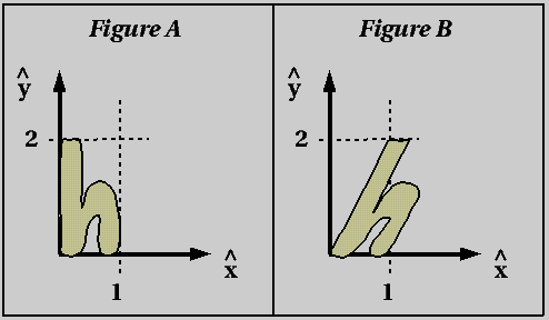
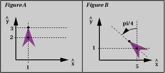
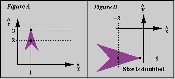
- For each of the two examples below, derive the transform required
to go from Figure A to Figure B. In each case, check your work by
using your transform to compute the location of the tip of the plane
in Figure B.
- Figure A below shows a three link robot arm. Link lengths are
l1, l2, and l3. These link lengths
represent the distance between robot joints, the black dots in the
figure (except for l3, which is measured from the last
joint to the tip of the link). Angles are expressed relative to each
joint, and so, for example, theta2 represents the rotation of link2
with respect to link1.
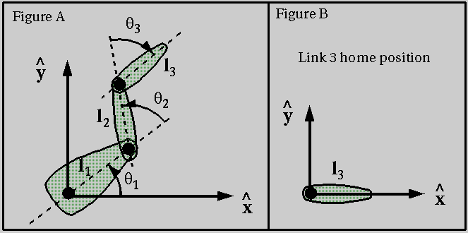
To animate the robot arm, we need to keep track of the current
transform for each of the links relative to a fixed "home" position.
Figure B shows the home position for link3. Write the transform to
move the vertices of link3 from the position shown in Figure B to the
position at the end of the robot arm in Figure A. This transform will
be a function of link lengths (l1, l2, and
l3), which are fixed over time, and joint angles (theta1,
theta2, and theta3), which will vary as the robot arm moves.
- Write the transform that should be applied to all of the points
on the boundary of Figure A below to create the italic character in
Figure B.