| |
| Application System Design | |||||||||||||||||||||||||||||||||||||||||||
|
4.1 System Architecture 4.1.1 Basic Architecture of the Program The basic architecture of the application is similar to Lam (2002)
C# implementation for the PC version. The whole architecture of
Pocket PC Ad Hoc Instant Messenger is very simple, involving three
classes:
4.1.2 System Data Flow Awareness Stage. First, at the beginning of the application,
each Pocket PC tries to broadcast its information (Pocket PC ID,
IP Address, to the Path reach other Pocket PCs, busy status, neighbor
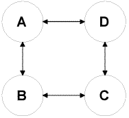
status, etc) to other Pocket PCs. If we consider the network topology
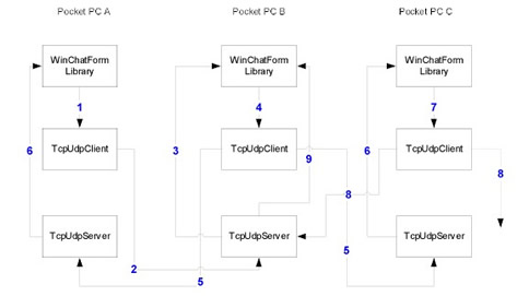
as Diagram 4.1, then the "Awareness" process is illustrated
in the Diagram 4.2.
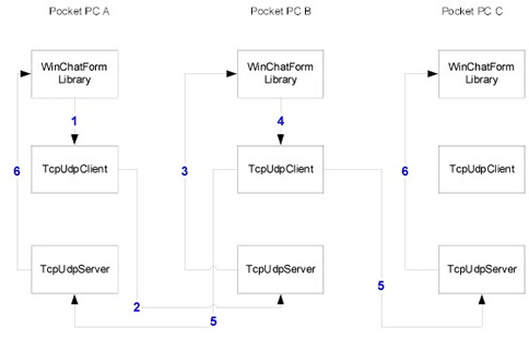
In the "Awareness" process, when Pocket PC node A joins the existing session of a wireless Ad Hoc network consisting of nodes B and C, the following steps would happen (in the following, we ignore the broadcasting packets sent to itself, because we will ignore those packet in the program anyway):
This process not only can happen during the startup stage, but also we can set a timer such that this process will re-broadcast in fixed time interval (for example, every 20 seconds). The basic steps are pretty much the same. Route Request Stage. Suppose that now A have both B and
C as its "Buddy". Although we can use the route path information
obtained during the "Awareness" stage, we still want to
implement this step for the reason that the path could be changed
after "Awareness" stage. Also, route request is an important
component of DSR protocol.
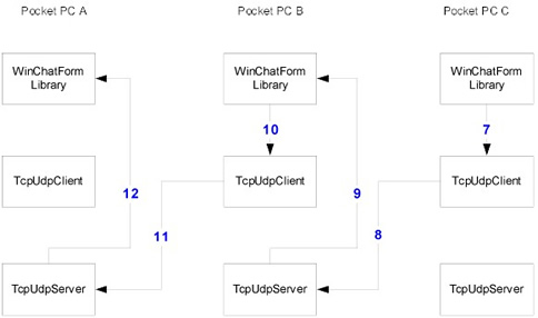
Route Reply Stage. Suppose that now C gets the "Route Request" packet, as well as the request from A to chat with C. C can send back the "Route Reply" Packet with information whether C wants to chat with A or not, as well as the Route information back to A. Even C does not want to chat with Node A, Node A can still receive a reply packet with the path from A to C (in this case, it is A->B->C). Because C already has the Path from A to C, Node C can just use the reverse path to piggyback the "Route Reply" packet without using broadcasting. Here are the steps (Diagram 4.4):
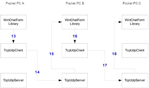
Chat Stage. Suppose that now Node A gets the "Route Reply" packet with the Path information (A->B->C). A can just utilize this path information to chat with C. Node A will put its message payload in the packet. Here are the steps (Diagram 4.5):
Hang-up Stage. Suppose that now Node A wants to "Hang-up" the chat session. Node A will send a "Hang-up" packet to C. The process is the same as the "Chat" stage. The only difference is the Packet Type. When C receives it, instead of displaying message payload, C will be notified that A wants to terminate the session. 4.2 XML-BASED DATA STRUCTURE FOR PACKET REPRESENTATION We use Extended Markup Language (XML) to represent the "Awareness", "Route Request", "Route Reply", "Chat" and "Hang-up" packets. Microsoft Compact Framework has an XML class that can parse and create XML-based packets easily. 4.2.1 Awareness Packet An Awareness Packet has 7 nodes; here is the XML structure of Awareness
Packet:
First Child node is the "Type"; the value is "Alive" for all awareness packets. "OIP" is the original IP address of the sender. "OID" is the first sender's ID who sends the packet. "CID" is the current ID in the broadcasting path. "Busy" describes the status of the original node; the value can be "Busy" or "Free". If the packets are sent from its neighbor, then "Neighbor" is "Yes ", otherwise, it is "No". "Online" describes the original sender's current online status, either "On" or "Off". "Path" records the broadcasting path the packet has gone through during the broadcasting. 4.2.2. Route Request Packet A Route Request Packet has 5 children nodes. First Child node is the "Type"; the value is "Request" for all Route Request packets. "OID" is the first sender's ID who sends the packet. "CID" is the current ID in the broadcasting path, while "DID" is the destination ID. "Path" records the broadcasting path the packet has gone through during the broadcasting route discovery. "BPath" is the reverse path for route discovered. Here is the XML structure of Awareness Packet:
4.2.3. Route Reply Packet
A Route Reply Packet has 7 children nodes. First Child node is the "Type"; the value is "Reply" for all Route Request packets. "OID" is the first sender's ID who sends the packet. "CID" is the current ID in the broadcasting path, while "DID" is the destination ID. "Path" records the broadcasting path the packet has gone through during the broadcasting route discovery. "BPath" is the reverse path for route discovered. "Status" displays the original node busy or free status. "Accept" will provide whether original node accept Chat request or not. 4.2.4 Chat Packet
A Chat Packet is similar to a Route Request Packet except that the "Type" is "Chat" and there is an additional "Payload" node. The "Payload" node is the place to store the chat payload message. 4.2.5 Hang-up Packet A Han-up Packet is similar to a Route Request Packet except that
the "Type" is "Hangup".
The 802.11b standard is aimed at the wireless Local Area Network (WLAN) market, and allows connections across ranges as great as 100 meters, depending on power level. Although this is good news for end user, it is bad news for testing our wireless Ad Hoc Pocket PC Instant Messenger application. For example, if we want to test the route request and reply capability of the application, because all Pocket PC can reach each other within 100 meters, then it is quite a challenge to test the application. Instead of hard coding the network logic into the programming application,
we design a configuration file that represents the network topology.
During the application initiation stage, each Pocket PC reads from
the configuration file into memory, thus holding the network topology
information in the memory for all future references. Then during
the data flow, even node A can reach C directly, we can use the
topology information to block or ignore the data flow directly between
Node A and Node C. The benefit of using a configuration file also
includes flexibility of modification. We can modify the configuration
file to reflect the network changes to meet our testing needs. Diagram 4.11 illustrates a network topology and its corresponding XML configuration files. In this case, A and C must use one other node to reach each other, B and D also need another node.
Diagram 4.12 illustrates a network topology and its
corresponding XML configuration files. In this case, A and D must
use two nodes (B and C) to reach each other.
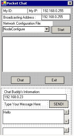
4.4 USER INTERFACE CONSIDERATION Transitional Windows Graphical User Interface (GUI) implements the "Form" concept. Software applications cerate or destroy Forms for users' interactions. During the design and implementation of the User Interface on Pocket PC, we find that Multiple Forms application does not achieve good performance. The original design uses two Forms: Buddy List Form and Chat interface Form. We find that when we switch between two Forms, Pocket PC does not promptly paint the screen due to its low CPU computing power and small memory capability. Based on this finding, we put both screens on the same User Form, with each screen being controlled by one Panel control. Depending on the user interaction, a Panel control would display at a proper position on the Pocket PC screen, while the other Panel control just hides itself. By using this approach, we dramatically reduce the delay between two screens. Here is the screenshot of the user interface design (Diagram 4.13):
Another consideration for the User Interface is the use of .Net Framework's MessageBox API. We uncover that MessageBox has a bug in the project implementation. Usually in a Windows environment, Call MessageBox API will display a MessageBox on top of the Forms. While in Pocket PC, this API will display at the bottom of the Form sometimes, thus causing confusion and error. We solve this problem by designing our own "MessageBox" using the same technique described before. Just use another Panel control to construct a group of Window controls to represent the "MessageBox". |
|||||||||||||||||||||||||||||||||||||||||||
|
Last
updated:
Wednesday, January 15, 2003
|
|||||||||||||||||||||||||||||||||||||||||||

