|
Appendix A
A.1 Abbreviations of Terminology
Appendix B
B.1 User Interface of the Statistical Analyzer
B.2 User Interface of the Send and Receive Files
Appendix C
C.1 conf.xml
C.2 GEN_basicInfo.xml
C.3 ADC_basicInfo.xml
C.4 Result_A.xml
C.5 DataAnalysis_A.xml
Appendix D
D.1 Source Code
APPENDIX A
This appendix gives all abbreviations of terminologies used in this thesis.
A.1 Abbreviations of Terminologies
| ACK |
Acknowledgement |
| AODV |
Ad hoc On-demand Distance Vector |
| AP |
Access Point |
| ARQ |
Automatic Repeat Request |
| BEST |
Bandwidth Efficient Source Tracing |
| BSA |
Basic Service Area |
| BSS |
Basic Service Set |
| CFP |
Contention Free Period |
| CP |
Contention Period |
| CPU |
Central Processing Unit |
| CRC |
Cyclic Redundancy Check |
| CSMA/CA |
Carrier Sense Multiple Access with Collision Avoidance |
| CTS |
Clear To Send |
| dBm |
"dBm" notation represents a measured power level in decibels relative to 1mW. |
| DBPSK |
Differential Binary Phase Shift Keying |
| DCF |
Distributed Coordination Function |
| DIFS |
DCF-IFS |
| DREAM |
Distance Routing Effect Algorithm for Mobility |
| DS |
Distributed System |
| DSDV |
Destination-Sequenced Distance Vector |
| DSR |
Dynamic Source Routing |
| DST |
Dynamic Source Tree |
| DSSS |
Direct Sequence Spread Spectrum (DSSS) |
| DTBS |
Distributed Time Bounded Service |
| DQPSK |
Differential Quadrature Phase Shift Keying |
| ESS |
Extended Service Set |
| FCC |
Federal Communications Commission |
| FDDU |
Fiber Distributed Data Interface |
| FEC |
Forward Error Correction |
| FHSS |
Frequency Hopping Spread Spectrum |
| FRC |
Forward Error Correction |
| GAF |
Geographical Adaptive Fidelity |
| HiperLAN |
High Performance Radio Local Area Network |
| IBSS |
Independent BSS |
| ID |
Identification |
| IEEE |
Institute of Electrical and Electronics Engineers |
| IP |
Internet Protocol |
| IR |
Infrared |
| ISM |
Industrial, Scientific, and Medical |
| LAR |
Location Aided Routing |
| LCC |
Logical Link Control |
| MAC |
Medium Access Control |
| MANET |
Mobile Ad-Hoc Network |
| MN |
Mobile Node |
| MPDSR |
Multi-Path DSR |
| MPDU |
MAC Protocol Data Unit |
| MSDU |
MAC Service Data Unit |
| NAV |
Network Allocation Vector |
| NDIS |
Network Driver Interface Specification |
| ODMRP |
On-Demand Multicast Routing Protocol |
| OLSR |
Optimized Link State Routing |
| PCF |
Point Coordination Function |
| PDA |
Personal Digital Assistant |
| PDU |
Protocol Data Unit |
| PIFS |
Point Coordination Function IFS |
| P2P |
Peer-to-Peer |
| QoS |
Quality of Service |
| RAM |
Random Access Memory |
| RC4 |
Ron’s Code or Rivest’s Cipher, a stream cipher designed by Rivest for RSA Data Security. |
| RTS |
Request To Send |
| RWM |
Random Waypoint Model |
| SADSR |
Security Aware Adaptive Dynamic Source Routing Protocol |
| SIFS |
Short Inter Frame Space |
| STAR |
Source Tree Adaptive Routing |
| SWS |
Sliding Window Size |
| TBRPF |
Topology Dissemination Based on Reverse-Path Forwarding |
| TORA |
Temporarily-Ordered Routing Algorithm |
| UDP |
User Datagram Protocol |
| WECA |
Wireless Ethernet Compatibility Alliance |
| WEP |
Wired Equivalent Privacy |
| Wi-Fi |
Wireless Fidelity |
| WLAN |
Wireless Local Area Network |
APPENDIX B
B.1 User Interface of the Statistical Analyzer
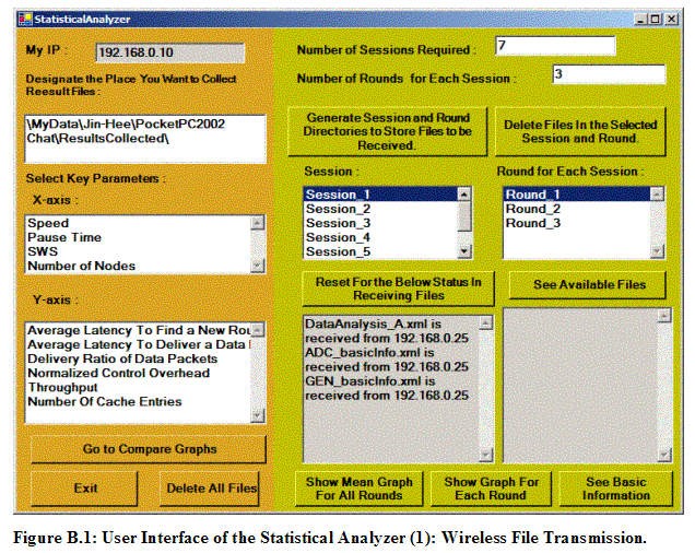
This appendix B shows user interfaces of the Statistical Analyzer used as a centralized data collector for all result files from each node and as an analyzer to generate appropriate graphs based on a selected set of x-parameter and y-parameter.
Each Pocket PC can transmit any file to this Statistical Analyzer running on a laptop. The left text box shows the files arrived at the Statistical Analyzer. The selected Session and Round indicates the specific directory to store the arriving files. The IP address of the Statistical Analyzer is set manually to 192.168.0.10, as Figure B.1 shows.
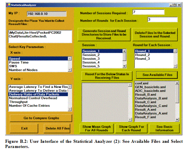
After the number of Session and Rounds is entered, the “Generate Sessions and Rounds Directories to Store Files to be Received” button will bring the generation of proper Sessions and Rounds. In the above example, there are 7 directories for 7 sessions, and 3 directories for 3 rounds within each of a session directory. Note that a user can designate the path that he or she wants to collect results files from all the nodes in the system in the upper left text box called the “Designate the Place You Want to Collect Result Files,” as shown in Figure B.2. Thus, the directories for the selected number of Sessions and Rounds will be created in the designated directory path.
In Figure B.2, the “See Available Files” button shows all files arrived under the designated directory in the Statistical Analyzer. Also, a set of x- and y-parameter can be selected on the left side of the interface. X-parameters are the variables that are manipulated to set up a specific scenario. Y-parameters are the five standard metrics to measure the performance of our wireless ad hoc messenger.
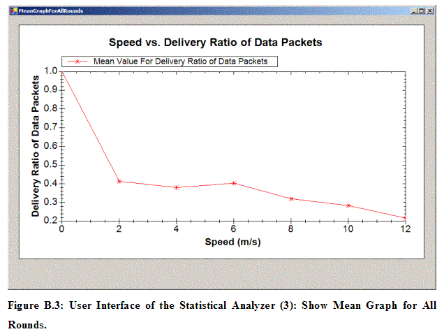
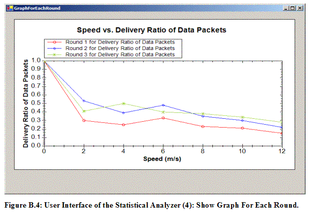
The “Show Mean Graph For All Rounds” button displays a graph with a mean value of three rounds based on the selected x and y parameter. The “Show Graph For Each Round” button demonstrates a graph with a value of each round. Figure B.3 and Figure B.4 show examples of respective graphs, where x-parameter is Speed and y-parameter is Delivery Ratio of Data Packet.
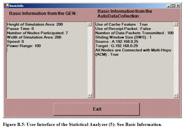
The “See Basic Information” button, located at the right bottom in Figure B.1, is used to display the basic information obtained in GEN_basicInfo.xml and ADC_basicInfo.xml files, as shown in Figure B.5.
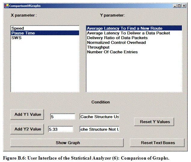
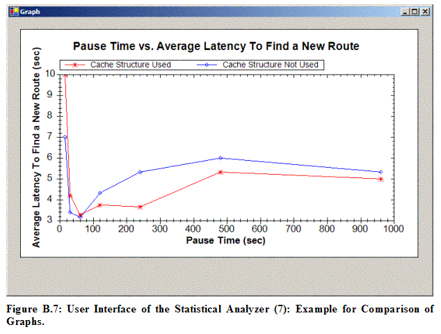
The “Go To Compare Graphs” button in Figure B.1 brings the above user interface to display two curves based on two different conditions. X and y- parameters can be entered by a user and y values can be manually added. The specific conditions for each curve are explained in the condition text box. The “Show Graph” button shows the specified graph, as shown in Figure B.7.
B.2 User Interface of the Send and Receive Files
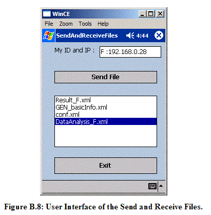
Figure B.8 shows the user interface for the Send and Receive Files application. This application is developed to transmit any file to the Statistical Analyzer. That is, this application transmits result files in each node wirelessly to the centralized data collector, the Statistical Analyzer.
APPENDIX C
C.1 conf.xml
The following XML file named conf.xml is generated based on input information described in another XML file named GEN_basicInfo.xml listed later in Appendix C.2. The input conditions are as follows:
Power Range: 100 m
Simulation Area: 200 m (Width)*200 (Height) m = 40,000 m²
Speed: 0 m/sec
Pause Time: 0 second
Participating Nodes: 7
Download conf.xml
C.2 GEN_basicInfo.xml
Download GEN_basicInfo.xml
C.3 ADC_basicInfo.xml
Download ADC_basicInfo.xml
C.4 Result_A.xml
Download Result_A.xml
C.5 DataAnalysis_A.xml
Download DataAnalysis_A.xml
APPENDIX D
D.1 Source Code
You can download source code for all programs developed in this thesis from here.
|

